How to Interpret Piping and Instrumentation Diagrams

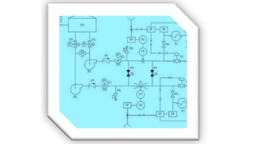
With a bit of smoke, a few mirrors and a degree in hieroglyphics, anyone can learn to read a P&ID. Piping and Instrumentation Diagrams is a topic that can benefit process, project and design engineers, business developers, operators, safety, maintenance and even management.

Interpreting Piping and Instrumentation Diagrams-Symbology

September 22, 2010. By Robert Cook
Get a thorough explanation of symbology as it relates to Piping and Instrumentation-controls symbology, tag identification, I/O devices, valve symbol, primary flow element, horizontal line types, dashes, and more.

As I mentioned in Part 2, the meanings of the various symbols used on P&IDs (aka, symbology) are defined on separate drawings called “Lead Sheets” (or Legend Sheets). These are your “secret decoder rings” to P&ID symbology interpretation. Every company that builds process plants should have a set of lead sheets customized to their particular ways and means.

Interpreting Piping and Instrumentation Diagrams

January 27, 2011. By Robert Cook
Learning to read and interpret piping and instrumentation diagrams via dry text-based articles (unlike those produced by yours truly) can be painful. To make this critical topic a bit more engaging, a series of videos intended to complement the series provided here are offered. They review the fundamentals of virtually every aspect of symbology and tag application.